This document provides an introduction to the SubSim physics xml specification. The described xml document controls the physical properties of an object in the simulation, including the objects physical shape, mass, and position, as well as the actuators and sensors that are connected to it.
Every entry in the SubSim Physics XML Specification file requires a name attribute. This name is what is used to access the devices in the SubSim Internal API and the SubSim HDT for the Eyebot API. If the entry does not have this name then SubSim may not behave in a correct manner.
It is also essential that the XML files are correctly specified. To check if an XML file has the correct syntax it can simply be opened in a browser, such as Microsoft Internet Explorer and the XML specification should be correctly displayed, or the location of a syntax error should be indicated.
This section of the XML describes the primitives (generic shapes) which define the collision response and bouyancy volume of an object in the simulation. There are three types of bodies:
Additionally each body has a mass and position specification. The position specification is a vector with three components: x, y and z.
< Sphere name="buoy">
	< Position x="0" y="0" z="0" />
	< Dimensions radius="0.5" />
	< Mass mass= "0.2" />
< /Sphere >
More information about the primitives can be found in the PAL documentation available here
There are 6 sensors currently supported by the XML description of the simulation object:
Every sensor has a 'connection' describing what primitive body the sensor is attached to (except the camera). The gyroscope and inclinometer have an axis vector describing the axis about which the angular rotation is measured. The PSD and Velocimeter also have an axis vector, but this axis describes the direction the sensor is facing. The PSD sensor also has a range description indicating the maximum range the PSD can detect.
< Contact name="c0">
    < Connection connects="submarine" / >
</Contact >
< Inclinometer name="inc0" >
	< Axis x="0" y="0" z="1" / >
	< Connection connects="submarine" / >
< /Inclinometer >
< PSD name="psd0" >
	< Position x="0" y="0" z="0" />
	< Axis x="0" y="-1" z="0" />
	< Range range="20" />
	< Connection connects="submarine" />
< /PSD >
  <Camera name="eyebot_cam">
	  <Resolution x="82" y="62" mode="RGB"/>
	  <Position x="1.0" y="0.06" z="0.0"/>
	  <Rotation x="0.0" y="270.0" z="0.0"/>
</Camera>
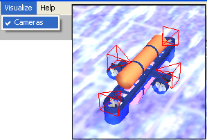
You can visualize the cameras in subsim so you can see there positions and adjustment. With subsim-menu Visualize->Cameras:
More information about the sensors can be found in the PAL documentation available here
There are only two main actuators types of use for propulsion in the SubSim application:
Additionaly, two more actuators exist for the simulation of water drag and buoyancy:
The buoyancy actuator simulation is only required if the underlying physics library that has been selected does not internally support buoyancy. The default examples included in the SubSim 1.0 distribution have the physics-library buoyancy disabled, and have buoyancy properties attached to the simulated bodies directly.
Just like sensors, every actuator requires as an input a connection to the body which it is attached to. The Propeller and Hydrofoil actuators also require an input position, which is the point at which the forces generated from the actuator is applied.
The propeller follows the simple lumped parameter model. A parameter, alpha, determines the ammount of thrust that should be generated, proportional to the input voltage to the propulsion system.
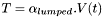 Lumped Propeller Equation
The lumped propeller equation describes the relationship between input voltage and thrust. An axis specifying the direction in which the thrust is to be exerted must also be specified for a propeller.
The hydrofoil is simulated using the lift equation described below:
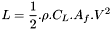 Lift Equation
Where,
CL is the lift coefficient,
a is the angle of attack.
p is the fluid density. (water is approx. 1)
Af is the frontal area.
L is the lift force.
V is the realtive velocity.
The lift coefficient is described by:
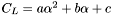 Lift Coefficient
Where a,b,c are experimentally determined.
The hydrofoil also requires the specification of two axis. One axis indicates the direction which the hydrofoil faces. This is used to measure the velocity of the liquid moving over the surface. The other axis indicates the direction in which the lift is applied.
< Propeller name="prop0" >
	< Position x="0" y="0" z="0.25"/>
	< Axis x="1" y="0" z="0"/>
	< Connection connects="submarine"/>
	< Alpha lumped="0.05"/>
< /Propeller/>
There is additional documentation on the hydrofoil and propeller available from the PAL website.
The graphical model used to depict the object can also be specified in the physics XML file. This is done in the following manner:
< GraphicsModel file="submarine.ms3d" />
Where submarine.ms3d is the name of the graphical submarine model file you wish to use to represent your submarine.