
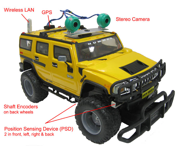
Hardware
We are using a model car resembling a Hummer from White Magic,
Canada. All remote control equipment has been taken out and replaced
with the following:
- Mini-ITX board running Linux (VIA EPIA-5000 PLE133 VIA C3 Eden
533 MHz CPU, 256 MB Compact Flash)
- Wireless LAN 11g USB stick
- Two USB web cameras for stereo imaging
- Servo for camera panning movement (HiTec)
- GPS module (TP-051)
- 5 PSDs (Position Sensing Devices), pointing forwards (2), right,
left & backwards. Infrared distance meter (10-50 cm).
- Speaker for speech synthesizer.
- Joystick for manual driving (connected to client PC)
- Shaft Encoders
Each back wheel is equipped with a shaft encoder. The shaft encoders
were made by modifying a serial mouse. The two mouse buttons are
mounted on the roof of the car. The encoder wheel has 250 slots, which
gives an resolution of 2 mm per pulse. The shaft encoders are used for
dead reckoning, e.i. calculating the
relative motion (translation in x and y direction and rotation) of the
car.
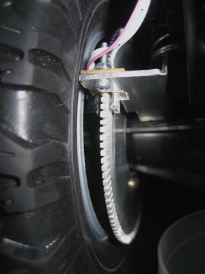
Figure 1. Shaft encoder on left
back wheel.
Way Point Following Using Path Planner
The robot travels autonomously to user specified way points, using a
collision free path planner.
- The graphical user interface on a client computer shows the map
that is available to the robot, see figure 2. The robot's position and
heading is indicated by a blue triangle, and the robot trace is
outlined by a red curve.
- The user adds one or several way points (yellow stars), e.i.
positions were the robot should travel autonomously, and sends them to
the robot by clicking 'Send Waypoints'.
- The robot plans a collision free path from the current position
to the first way point and between consecutive way points using the
heuristic best-first search algorithm, A*. The
planned path is simplified to a few intermediate way points (shown as
green stars in the user interface) that connects the current position
with the user provided way points.
- The robot starts traveling to the way points, one at a time.
- A priori unknown obstacles that are registered by the PSD sensors
while traveling are added to the map as temporary obstacles and shown
as purple rectangles. The size of the rectangles is the resolution of
the occupancy grid that constitutes the internal map. Similarly, sites
that according to the map are occupied by an obstacle but in fact are
empty (as sensed by the PSD sensors) are registered as temporarily
empty, shown as white rectangles in the user interface.
- If the planned path (consisting of the list of way points) is no
longer transversable as a consequence of the added obstacles, is a new
path planned to ensuring that these are avoided as well.
Communication
The client computer (running the user interface) and the robot
is connected to the same Wireless Local Area Network (WLAN) and
communicate using the User Datagram Protocol (UDP).
Localization
The initial position and heading is known to the robot. Dead
reckoning is used to update the current position estimation. The dead
reckoning algorithm utilizes sensory inputs from the two shaft encoders
mounted on the back wheels.
Speech Feedback
Speech feedback is given whenever a user defined waypoint is
reached, e.g. "Reached first way point" or "Reached third way point.
Mission was successfully completed".
Festival, a
free linux speech syntehesizer is used to achieve this.
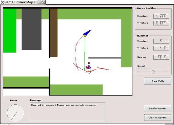
Figure 2. Screen shot from the
graphical user interface on the client PC. Blue triangle shows the
position of the robot. Red curve is the robot trace. Yellow stars are
way points added by the user. Small green stars are intermediate
way points added by the planner in order to avoid obstacles. Purple
rectangles are obstacles that where registered by the PSDs during the
run.
Links
Object Tracking
Color and size of the object and the background noise is measured
during the learning phase.
The detected object is tracked while avoiding obstacles in the tracking
phase.
One of the cameras are used for tracking the object and the 5 PSDs are
used for obstacle avoidance.
Learning phase
The object is shown to the robot which measures
and records a hue (color) histogram. The histogram is used to construct
a color filter. The output of the filter is a grey-scale image, were
the intensity of each pixel is proportional to the occurrence of that
color (hue) in the measured histogram (see figure 3).
The object is placed approximately 1 meter from the camera and the size
of the object is recorded (sum of the pixel values in filtered image).
The object is removed and the background noise is measured.
Tracking phase
The color filter is applied to the camera image.
Colors that are similar to the tracked object gets a high intensity
(light grey/white) and others get low intensity (dark grey/black) (see
figure 3b). The intensity values in the filtered image are summed up
row-wise (blue curve in figure 3b) and column-wise (red curve in figure
3b). The two curves are low-pass filtered. The maxima of respective
curve is taken as the estimated object position. The robot turns left
if the object is in the left 1/3 of the image, right if its in the
right 1/3 or goes straight otherwise.
The speed of the robot depends on the estimated distance to the object.
The distance estimation is done based on the square root of the sum of
pixel intensities in the filtered image. The speed is higher if the
object is far away. If the sum of the pixel intensities in the filtered
image is less then 2 times the background noise (as measured during the
learning phase) the object is regarded as absent and the robot stops.
If the sum of the pixel intensities in the filtered image is greater
then the value measured during learning with the object on 1 meter
distance, the object is regarded to be close and the robot
stops. Obstacles are avoided using the 5 PSDs and motor stall detection
while tracking the object.
Figure 3. (a) Camera image with
tracked object in the foreground.
(b) Image after the color filter has been applied. Green cross hair
indicates estimated object position.
Links
Simple Obstacle Avoidance
Obstacle avoidance using the 5 PSDs and motor stalled detection.
Links
Currently working on the project
- Kalle OHLSSON <kalle.ohlsson(at)gmail.com>, visiting Msc
student from Chalmers University of
Technology, Gothenburg, Sweden.
- Kasun LIYANAARACHCHI, final year mechatronics student, University
of Western Australia.
not so Grand Challenge, Mobile Robot Lab, UWA
Thomas
Bräunl