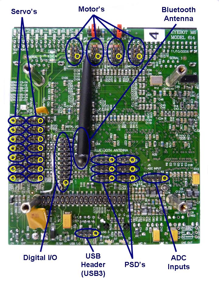
This is a short description on how to install EyeBot, hardware version M6. The EyeBot system itself is already completely assembled, so you are able to start right away. Yellow dots in the drawing indicate pin no.1 of the corresponding connectors, For the Servo's the yellow circle indicates which pin to connect the yellow/white wire to.
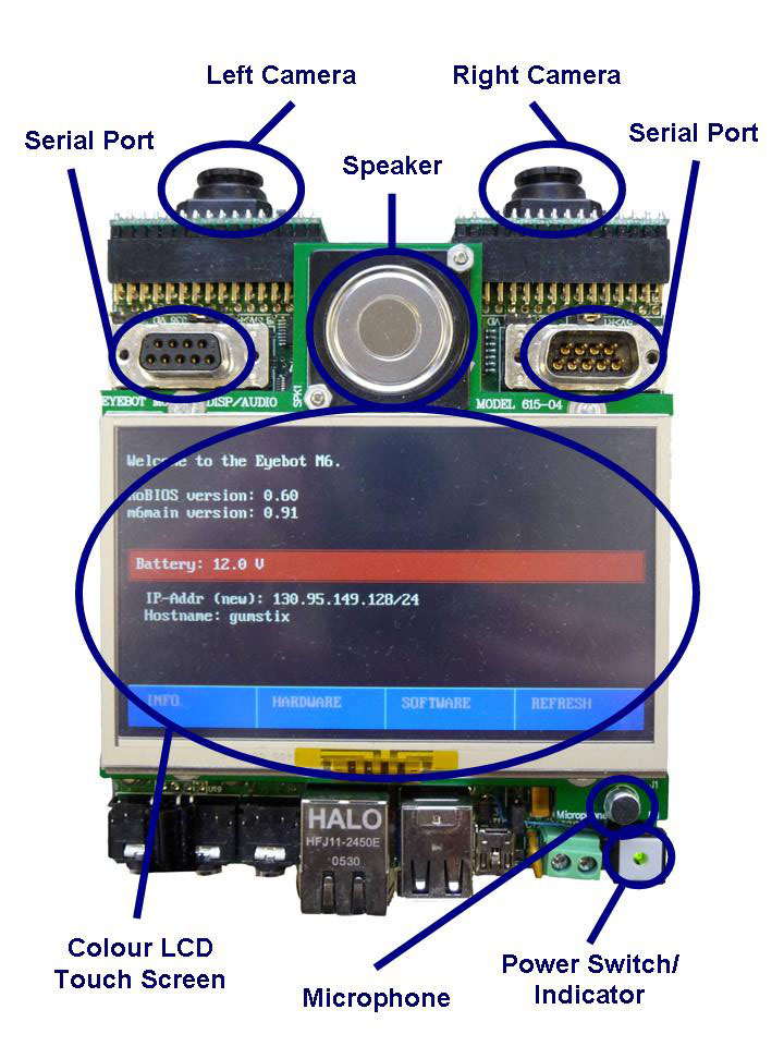
Camera
To work with EyeBot, two
EyeCam CMOS digital
color cameras (352x288 in bayer pattern) are being used. The cameras
plug directly into the controller board (make sure
you connect pin no.1 where indicated, the camera board should face down).
LCD
The LCDisplay is already connected to the EyeBot. The screen is cabable of
displaying text and graphics with a large number of colours. The screen can
display a max text resolution of 60 characters by 17 lines. The Pixel area of the full screen is 480x272
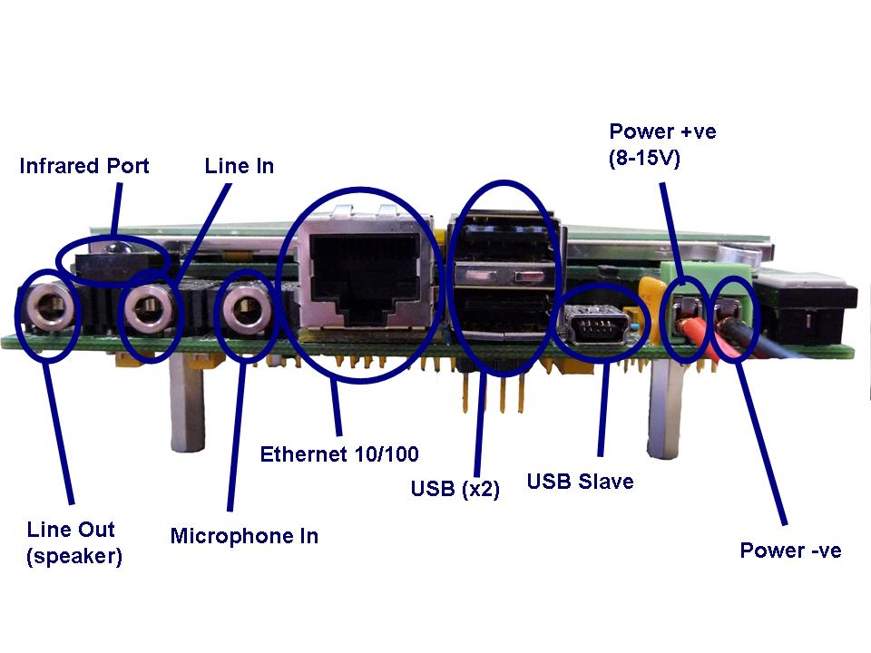
Power Supply
There is a connector for power supply with pins labelled "+" and "-". Connect a
power supply between 8 and 15 Volts. 12 Volts is highly recommended for
versatility and stability.
The board is equipped with a reconstitutable fuse.
However, supplying a high voltage or reversing the voltage may damage the board.
Serial Connector
A standard 9-pin RS-232 extension cable can be used to connect EyeBot's serial-1
port to a PC, Mac or workstation. This will give you access to terminal shell
functionality on the eyebot. Please note commands are linux not Windows commands. Alternatively connect the ethernet port into
a network and you will be able to use putty or the ssh command in a linux shell to log in.
DC Motor and Encoder Connectors
There are 4 connectors for DC motors and encoders. Four motor drivers
are integrated in EyeBot. The pinouts are not pin compatible with the M5 version so check.
from:
Microphone
A minature microphone is built-in on the front side of the EyeBot. Currently
too weak to use, please plug in an external mike to connector J3 .
Extension Connectors
There are 2 separate connectors for adding additional I/O.